EE3041 DSP on FPGA Big Project Lab 1 - Waveform Generator
Lab 1 for EE3041 DSP on FPGA Course at HCMUT
Lab 1 - Waveform Generator
Objective
The primary objective of this lab is to design and implement a versatile waveform generator using an FPGA. The generator should be capable of producing various types of waveforms with adjustable parameters such as frequency, amplitude, and duty cycle. Additionally, the system should be able to inject noise into these waveforms. The final implementation will be demonstrated on an FPGA using the DE10 Standard Development Kit (DE2 will NOT be accepted in this lab or any subsequent labs), with the output displayed on an oscilloscope.
A Note about Collaboration
Big project is to be accomplished in groups. All work must be from your own team members.
Hints from others can be of great help, both to the hinter and the hintee.
Thus, discussions and hints about the assignment are encouraged. However, the project must be coded and written up in groups (you may not show, nor view, any source code from other students’ groups). We WILL use automated tools to detect copying.
Use Emails/LMS to ask questions or come visit us (203B3) during office hours.
We want to see you succeed, but you have to ask for help.
Overview
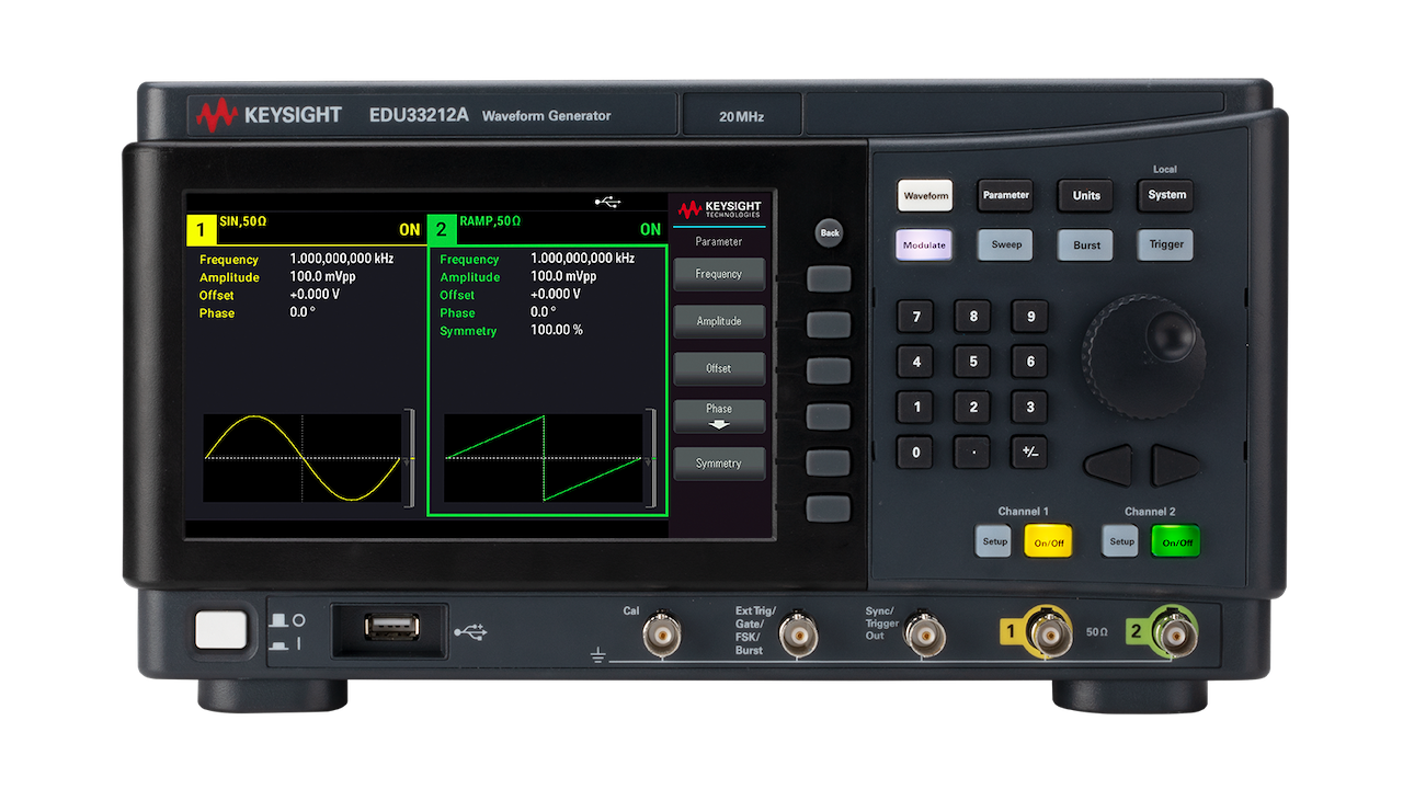
In this lab, you will design a waveform generator capable of producing a variety of waveforms such as sine, square, triangle, sawtooth, ECG, and noise. The generator should allow for the adjustment of key parameters including frequency, amplitude, and duty cycle (where applicable). Additionally, the system should be able to inject noise into the generated waveforms.
Background
Waveforms
Waveforms are graphical representations of the variation of a signal over time. Common types of waveforms include:
- Sine Wave: A smooth, periodic oscillation.
- Square Wave: A periodic waveform that alternates between two levels.
- Triangle Wave: A periodic waveform that ramps up and down linearly.
- Sawtooth Wave: A periodic waveform that ramps up linearly and then drops sharply.
- ECG Wave: A waveform that mimics the electrical activity of the heart.


Waveform Generator
A waveform generator is an electronic device that can produce these various types of waveforms. In this lab, you will design a digital waveform generator using an FPGA, which allows for precise control over the waveform parameters.
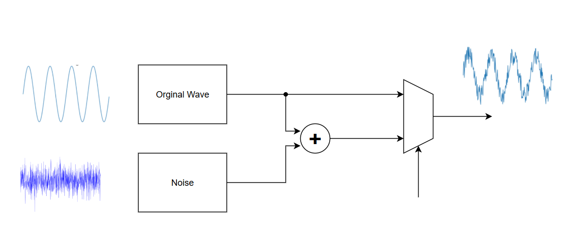
The waveform generator must include the capability to inject noise into the original waveforms. This feature is essential for Lab 2, where you will be required to filter out the injected noise using a designed filter. Ensure that the noise injection is controllable and can be adjusted in terms of frequency, amplitude, you can use a pseudo random generator (eg. LSFR) to generate the values.
DE10 Standard Development Kit
In this Lab 1, we will use the DE10 Standard Development Kit, a powerful FPGA development platform based on the Cyclone V SX SoC—5CSXFC6D6F31C6N. The DE10 kit offers a wide range of resources, including:
- 110K LEs, 41,509 ALMs
- 5,761 Kbits embedded memory
- 6 FPGA PLLs and 3 HPS PLLs
- 2 Hard Memory Controllers
- 112 DSP blocks
- 64MB (32Mx16) SDRAM on FPGA
- Wolfson WM8731 24-bit Audio CODEC
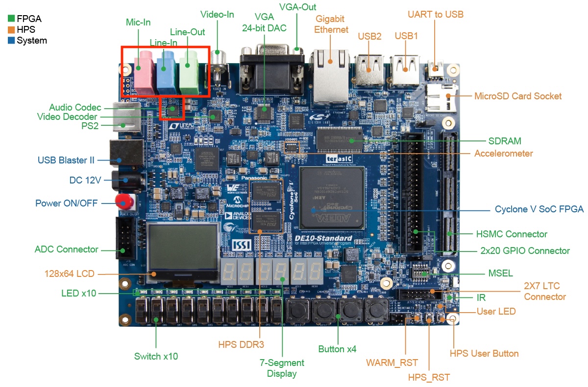
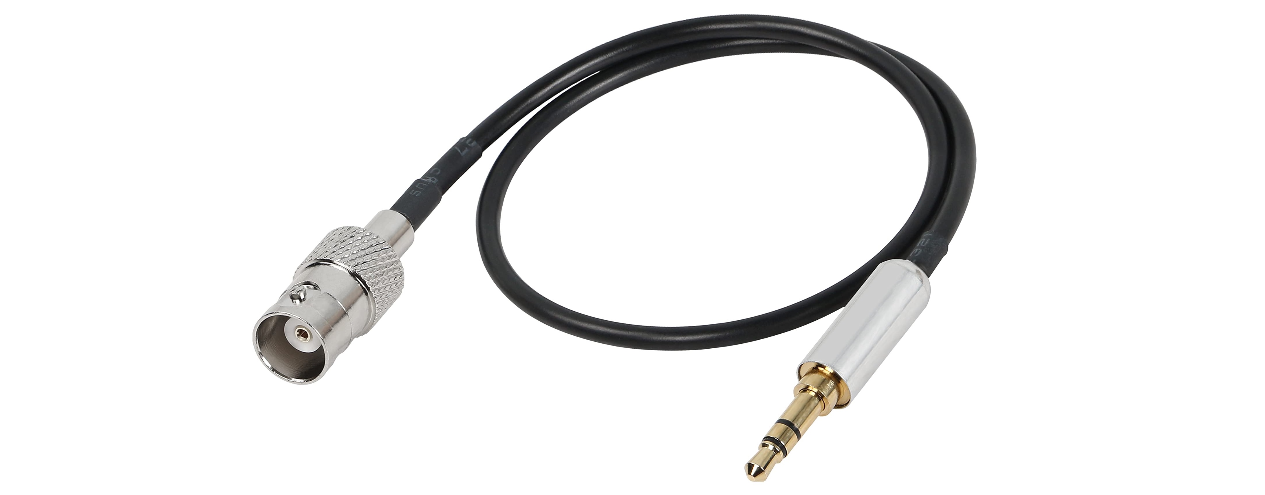
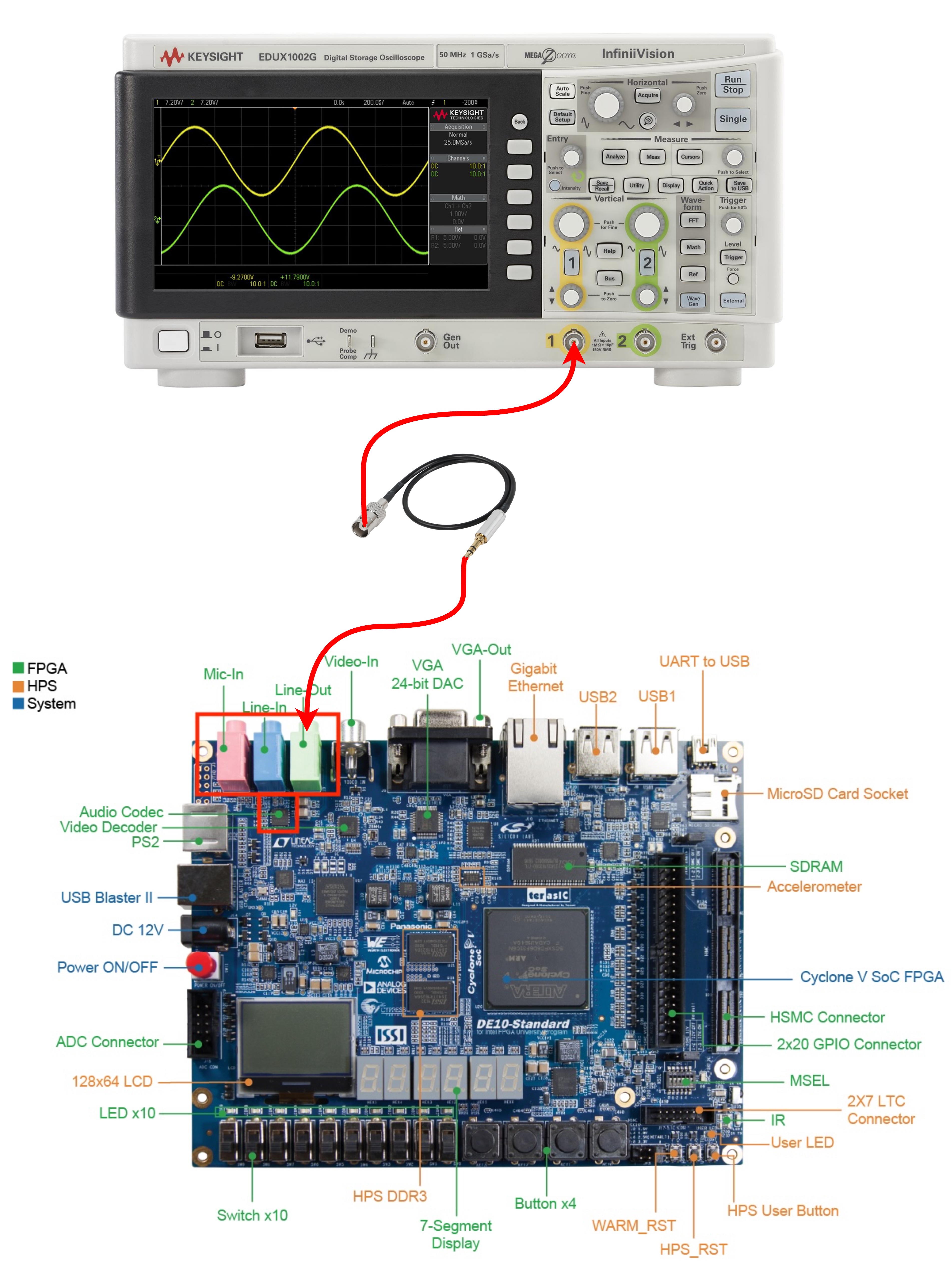
This makes it ideal for digital signal processing (DSP) tasks. In this lab, we will use the Audio CODEC as a DAC to output the 24-bit processed data through the audio output port. Additionally, in Lab 203B3, we provide a 3.5mm jack to BNC cable, which you can use to connect the output to an oscilloscope for visualizing the signal.
Assignment Overview
- Design the Waveform Generator:
- Choose an appropriate hardware description language (HDL) for your design.
- Create modules for generating different types of waveforms.
- Implement controls for adjusting frequency, amplitude, and duty cycle.
- Add functionality to inject noise into the waveforms.
- Simulate the Design:
- Use simulation tools to verify the correctness of your design.
- Ensure that all waveforms and parameters can be correctly generated and adjusted.
- Implement on FPGA:
- Use the DE10 Standard Development Kit to implement your design.
- Connect the FPGA to an oscilloscope using the built-in CODEC and a 3.5-to-BNC cable.
- Verify the output on the oscilloscope to ensure it matches the expected results.
Demonstration on FPGA
To showcase your waveform generator on the DE10 Standard Development Kit, your implementation must meet the following requirements:
- Waveform Generation: The system should generate multiple waveform types, including sine, square, triangle, sawtooth, and ECG. Users must be able to adjust frequency, amplitude, and duty cycle (if applicable) using switches and buttons. The implementation method is flexible.
- Noise Injection: The system should support injecting noise into the generated waveforms.
- Waveform Visualization: The output waveform must be displayed on an oscilloscope using the FPGA’s built-in CODEC and a 3.5mm-to-BNC cable.
For Credit
- 1 point: Demonstrates a basic understanding of waveform generation and designs the specifications for the waveform generator. This includes defining the types of waveforms (sine, square, triangle, sawtooth, ECG, noise) and the adjustable parameters (frequency, amplitude, duty cycle).
- 1 point: Completes the RTL design for the waveform generator, ensuring it aligns with the given specifications. At a minimum, the design must include sine and square wave generation, and noise injection functionality. These points are awarded only if you successfully simulate and verify the generator’s functionality by producing at least one waveform type.
- 1.5 points: Additional waveforms are awarded as follows:
- Simple waveforms (e.g., triangle, sawtooth): 0.25 points each.
- Complex waveforms (e.g., ECG): 0.75 points each.
- 1.5 points: Successfully simulates the waveform generator design with the provided input parameters. Your analysis should explain how well the generator performs, including the accuracy of the waveforms and the responsiveness of parameter adjustments.
- 2 points: Synthesizes the design and checks the synthesis report to ensure the design is synthesizable and meets timing constraints.
- 3 points: Performs a live demo on an FPGA, demonstrating real-time waveform generation and parameter adjustments. The output should be displayed on an oscilloscope via the built-in CODEC and a 3.5-to-BNC cable.
- Bonus points:
- Suggest and implement your own innovative improvements to the waveform generator, such as additional functionality or optimizations.
- If your waveform generator results are not optimal, provide a detailed analysis explaining why the results are insufficient and propose a solution to improve it. Even if the performance is not ideal, a well-explained analysis can still earn bonus points.
Reporting Requirements
Your report should be concise but detailed enough to clearly explain your design process, simulations, and results. Make sure to:
- Show clear evidence of how your generator performs with the provided input signals, including graphs or waveforms and analysis.
- Include the synthesis report and analyze the results, such as resource utilization, timing constraints, and operating frequency.
- Provide an image of the oscilloscope output if you successfully implemented the design on the FPGA.
- If the filter doesn’t perform well, offer a detailed analysis of why the results are not as expected and propose improvements or solutions.
Your report should focus on quality rather than length. While it shouldn’t be excessively long, it needs to be thorough and well-structured. Points will be deducted for poor reporting, such as missing key details, insufficient analysis, or unclear presentation. Make sure to present your work in a professional and readable format.
How To Turn In Your Solution
This semester we will be using LMS, simply submit the zip file with your reports and codes.
Demos and Late Penalty
We will have demo / presentation times on of class times on or near the due date. Since we will demo from the files in your zip, it is possible that you’ll demo on a following day.
Define Late: Lateness is determined by the file dates of your submission on LMS.