EE3041 DSP on FPGA Big Project Lab 3 - Audio Equalizer
Lab 3 for EE3041 DSP on FPGA Course at HCMUT
Lab 3 - Audio Equalizer
Objective
The objective of this lab is to design, implement, and test an audio equalizer using FPGA technology. You’ll gain practical experience in digital filter design and FPGA-based digital signal processing (DSP). By the end of this lab, you should have a functional equalizer capable of adjusting specific frequency bands to enhance or attenuate certain audio features.
A Note about Collaboration
Big project is to be accomplished in groups. All work must be from your own team members.
Hints from others can be of great help, both to the hinter and the hintee.
Thus, discussions and hints about the assignment are encouraged. However, the project must be coded and written up in groups (you may not show, nor view, any source code from other students’ groups). We WILL use automated tools to detect copying.
Use Emails/LMS to ask questions or come visit us (203B3) during office hours.
We want to see you succeed, but you have to ask for help.
Overview
In this lab, you will design an audio equalizer capable of adjusting multiple frequency bands. You have the option to use either FIR (Finite Impulse Response) or IIR (Infinite Impulse Response) filters, depending on your preference and understanding of each filter’s characteristics and trade-offs. At a minimum, the equalizer should have three basic frequency bands: bass, mid, and treble. However, if you aim to achieve a higher score, consider dividing the frequency spectrum into finer bands—such as a 10-band equalizer covering 20Hz to 20kHz. Adding more bands will allow more precise control over the audio signal and demonstrate advanced filter design capabilities.
If you want to aim for a higher grade, your equalizer should allow real-time changes to frequency gain. Gain can be adjusted using the DE10 board’s switches and keys or by implementing a program that communicates with the FPGA to control the filter settings dynamically.
The lab includes the following steps:
- Understanding the filter theory for audio equalizers.
- Designing filter architectures for different frequency bands.
- Coding the filter in HDL and verifying its performance through simulation.
- Testing the filter with real audio input and outputting equalized audio through a speaker.
Background
Audio Equalizer
An audio equalizer is a tool that allows users to modify the amplitude of certain frequency ranges (bands) within an audio signal. Common frequency bands include bass (low frequencies), mid (midrange frequencies), and treble (high frequencies). By adjusting these bands, you can enhance or reduce certain elements of the audio for a more customized listening experience.
Equalizers can be built using either FIR or IIR filters that you have implemented in previous labs.
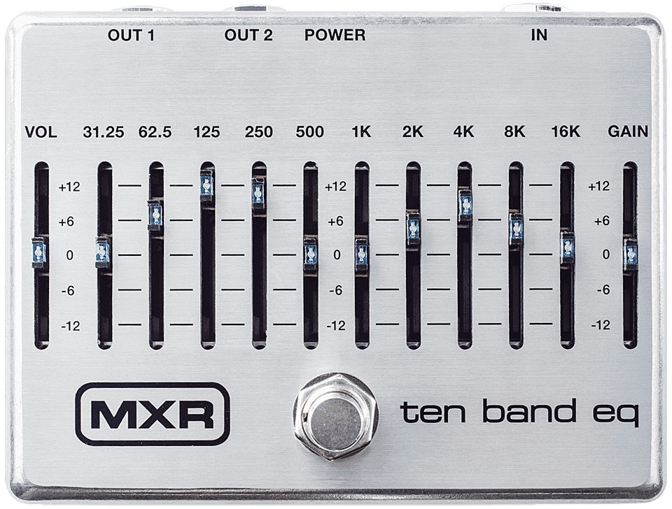 MXR M108S 10 Band Equalizer
This is an example block diagram for a 3-band equalizer. In this design, the audio signal is divided into three distinct frequency bands using FIR filters: bass, mid, and treble. Each band has an adjustable gain, allowing you to increase or decrease the amplitude of the audio signal within that specific frequency range.
 Example of a 3-band qualizer
Assignment Overview
Your task is to create an audio equalizer with at least three frequency bands: bass, mid, and treble. For this lab, you are required to build your own testbench and obtain an audio sample to thoroughly test your design. The testbench should simulate the filter’s performance and allow you to verify that each frequency band is being properly adjusted according to your equalizer settings. Ensure that the audio sample you use has a range of frequencies so that the equalizer’s effect on each band can be clearly observed.
Demonstration on FPGA
If you’re aiming for a high grade, you’ll need to implement your design on the FPGA using either the DE10 Standard Development Kit or DE2 Standard Development Kit. The requirements for this lab are as follows:
- Demonstrate the basic functionality of your equalizer, showing that each band (bass, mid, and treble) can be adjusted individually.
- Provide a method for adjusting the bands in real-time. This can be done using the board’s switches and keys or, for a more advanced solution, through a program on your computer that communicates with the FPGA, allowing you to adjust the frequency bands dynamically.
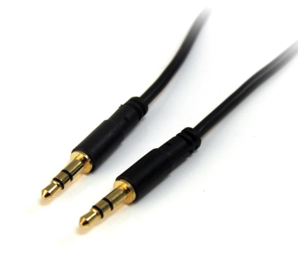
- Perform a live audio test by playing an audio sample from an external device (e.g., laptop or phone) connected to the board’s microphone jack. Pass this audio through your equalizer, outputting the modified audio to a speaker so that the effect of each band adjustment on the sound can be clearly heard. This demonstration should highlight the real-time performance and audio quality of your equalizer design. You could use the 3.5mm to 3.5mm audio cable to connect the audio output of your laptop to the audio input of the board. The audio output of the board can be connected to a speaker.
For Credit
Total: 10 points (max), plus bonus.
| Criterion (weight) | Emerging / Below Standard | Progressing / Approaching | Proficient / Meets Standard | Advanced / Exemplary |
|---|---|---|---|---|
| Equalizer Understanding (0.5 pt) | Little/no understanding of equalizers or per-band filter needs | Partial understanding; band filtering explanation vague | Demonstrates understanding of equalizers + basic per-band filter requirements | Thorough, discusses trade-offs between band filter types & design choices |
| Filter Choice & Specification (0.5 pt) | No justification for FIR/IIR choice; spec missing | Choice stated but weakly justified; spec partial | Well-reasoned FIR/IIR (or combo) choice + complete spec | Justification rigorous, spec precise, anticipates trade-offs (latency, resources) |
| Working Equalizer Implementation (2 pts) | Not implemented, or bands missing/non-functional | Implemented but not fully functional across bands; sim missing | Working 3-band (bass/mid/treble) equalizer, simulated & verified | Clean, robust, all bands verified, well-organized RTL |
| Filter Design Verification (2 pts) | Not simulated, or sim doesn’t verify specs | Sim incomplete; design misses spec for some bands | Verifies each band meets required specs in simulation | Thorough, well-documented, plots/data show spec met incl. edge cases |
| Synthesis (2 pts) | Not synthesized / not synthesizable | Synthesizes but report unchecked or issues unresolved | Synthesizes; report checked to confirm synthesizability | Report carefully analyzed (utilization, timing, fmax), results discussed |
| Real-Time Gain Control Demo (3 pts) | No demo, or gain control non-functional | Partial — some bands unreliable or poor audio quality | Real-time per-band gain control via switches/keys, external audio source | Polished, reliable, distinct high-quality effect per band |
| Bonus (uncapped) | No bonus attempted | — | Extra bands, external gain-control program, parameterized design, own idea, suboptimal-result analysis, or social media content (e.g., short demo video/post) | Strong contribution (many extra bands, PC-controlled gain, fully parameterized design, polished social media content with engagement) or rigorous validated analysis |
Reporting Requirements
Your report should explain your design choices, simulations, and results. Ensure it includes clear evidence of your filter’s performance, such as waveforms and graphs, and a detailed analysis of any issues encountered. For more details, refer to Lab 2 - FIR and IIR Filters, Reporting Requirements
How To Turn In Your Solution
This semester we will be using LMS, simply submit the zip file with your reports and codes.
Demos and Late Penalty
We will have demo / presentation times on of class times on or near the due date. Since we will demo from the files in your zip, it is possible that you’ll demo on a following day.
Define Late: Lateness is determined by the file dates of your submission on LMS.